

How To Design A Bulbasaur Plant Pot
- Jul 16, 2018
- 4 min read

I am quite sure that I am not the only one when I say that houseplants and flowers are one of my favorite things. They add color to the surrounding and simply look beautiful! Nevertheless, it's sometimes hard to get a pot that is as pretty as the plant itself. But you can always make your own! In this article, I am going to take you through a process of designing and printing your own Bulbasaur flower pot using CAD. SelfCAD is the program that we are going to use. The reason why I picked this one is because it has good design, advanced tools and is easy-to-use at the same time. Good news is it also has a built-in slicer, so you can 3D print what you design straight away!
Let's kick off!
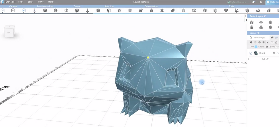
Step 1: Creating the Basic Shape
To start designing the model above, first, we need to have a reference image.
Once you have your reference image, go to View> Reference Image and this will direct you to upload your image.

Once you have imported the image, select a cube from the basic shape section and set the width segments to 4 then finalize the shape.
Selec the Move tool from the Transformations section and move the cube shape below the reference image.

Select the Scale tool and use it to scale down the object so that it can be like the one shown below.

Go to the Scene section (found on the left-hand-side) and set the Opacity to 90.
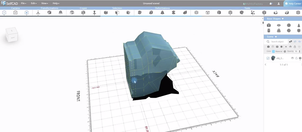
Select the Vertex selection tool from the selection section and use it to select the vertices of the model. Select the Polygon select tool and use it to select the top polygons.
After this, select the Extrusion tool from the Tools section and set the Amount settings to 27 and click Apply. Select the Vertex selection tool again and use it to select and move the vertices to be like the one shown in the 4th image above.
Select the Edge Selection tool and use it to select one of the edges of the model and use the Move tool to move it up.
Use the Polygon, Vertex and Move tool to modify the model further to be like the 5th image above. Check the video above to learn how to achieve this.
Step 2: Creating the Width of the Object
To create the width of the object, we need to add another reference image.
In the View section, select Reference Image and upload your image.
Once you import the reference image, select
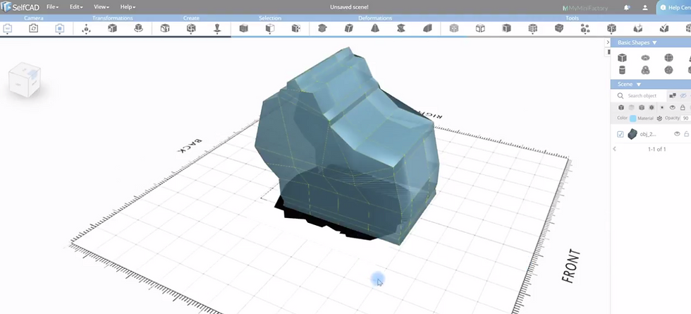
Position the object in the middle of the reference image. You can do this using the Move tool. Select the Rotate tool and place the X, Y and Z values to zero.
Select the Polygon selection tool and use it to select the right face of the model. After selecting, take the Extrusion tool and increase the Amount settings to 41 to add more segments to the model as shown below.
Step 3: Further Modification of the Model
Add another reference image with the Top view.
Use the Selection, Scale and Move tools to shape your model as shown below.

To learn how to use the selection and Extrusion tools to modify the object, check the video above.
Step 4: Creating the Eyes and Hole of the Flower
To create the flower, we will be using the Drawing tool to draw the hole, Vertex selection and Scale tools to resize the Hole and Stitch and Scoop tool to extract the Hole drawing in order to remain with the hole only.
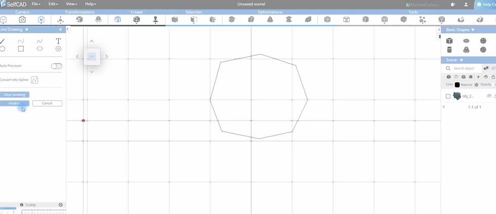
Select the Drawing tool from the Create section.
Select the Line drawing tool and use it to draw the hole as shown below then finalize it.
Use Scale tool to resize the drawing and align it on top.
Select the Vertex selection tool to select the Vertices of the Model and use the Move tool to move the hole in order that It may align itself on top of the model.
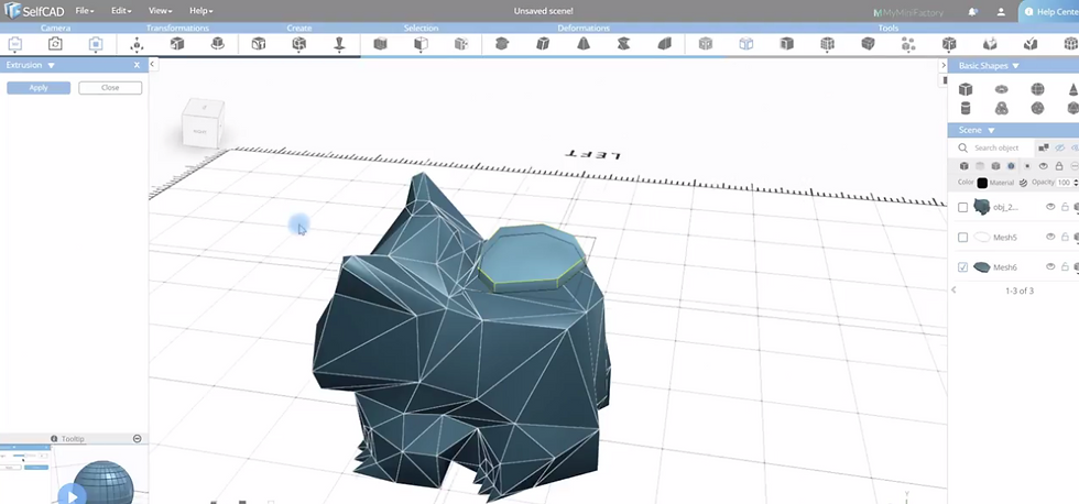
Select the Stitch and Scoop tool from the Tools section and select Difference option (Ensure the hole model and the Bulbasaur mode.
After doing this, select the Hole drawing and click Apply. This will be able to leave a hole on top of the model as shown below.

Select the sections that are not well aligned using the Polygon selection tool and delete them in order that a perfect hole may be created.
To deepen the hole, select the top polygons and use the Move tool to move it downwards.
To create the eyes, repeat the same process.
Once you finish, don't forget to correct the vertex of the entire model because of the changes brought about by the hole and eyes.
Step 5: Slicing and Printing
SelfCAD has a built-in Cura slicer that helps you slice your model.
To slice the model, go to File>3D Print or use Alt+ P keys.
After you select 3D print, you will be redirected to a section where you can select your printer.
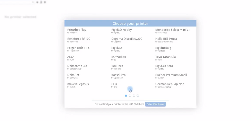
After selecting your preferred printer click "Generate G-Code", and this will generate G-code that you will send to your printer. There is also an option where you can customize your settings.

I recommend you set Wall thickness and Top/Bottom settings to 1.2.
After this, you will be able to see how the layers of the model have aligned themselves. Check the image below to see how mine have aligned themselves.


Click save the G-Code then 3D print your model.
Comments